Contents
- Index
- Previous
- Next
Band and Grease Groove Detail

When the In-Case value is initially calculated, the base band, gas check shank (if any), body band and grease groove lengths are automatically calculated. In order to enable a more simple process of mold fabrication setup, these values are initially calculated so as to be either a multiple of 0.005" or evenly divisible by 0.005".
You may edit your in-case value to arrive at initial values rounded off to 0.005" by following this procedure.
First, be aware that the software recognizes the driving bands as three separate units defined here as A, B and C.
.
A. If crimp groove(s) are present, the Crimp Groove Interval Bands (if any) and the Crimp Groove Bottom Band.
B. The Base Band, composed of the gas check (if any) shank and the Lower Band.
C. Any (all or none) Body Bands that are located between the Base Band and the Crimp Groove Bottom Band.
The software always draws a Base Band and may or may not, according to the values entered draw the Body Band(s) and/or the Crimp Groove Band(s)
#1. Start with an in-case value that is evenly divisible by 5 ( 0.050, 0.040, 0.055, 0.045, etc.).
#2. If there is a crimp groove or grooves, subtract the length of the crimp groove(s) and length of the interval(s) from the in-case value.
#3. Next, if a gas check configuration has been selected, the software will have calculated a minimum gas check shank length, rounded off to the nearest 0.005", and entered the value into the Gas Check Length Field. Subtract this value from the remainder value arrived at in step #2 and go to step #4.
#4. If there are no crimp groove(s), divide the value obtained in step #3 by 6. If crimp groove(s) are present, divide the value obtained in step #3 by 7. and round off the decimal number result to the nearest 0.005". Use this value as the Crimp Grooves Lower Band Length value.
#5. Now, take the in-case length determined in step #1 and subtract the OAL of the Crimp Groove Band ( crimp groove(s) + interval(s) + lower crimp band length).
#6. Then, use the value found in step #4, multiply it by 5 and subtract the product from the value found in step #5
#7. The net result is the length of the driving band and the gas check shank (if present). Enter that value in the Base Band Length Field.
#8. Enter a Groove/Band ratio of 1, a value of 2 for the number of Body Bands and press the tab key to auto-calculate the remaining values. There are now 2 body bands, 3 grease grooves and one crimp groove band of all the same length and rounded off to the nearest 0.005" inch.
Adjust and edit your values as desired.
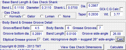
The Groove Bottom Diameter is initially determined when the As Cast Diameter is entered and may be edited as desired.
The Band Length value is determined by the Groove/Band Ratio and the number of Body Bands.
The Groove side-angle value is the angle that will be formed by the sloping side of a rectangular groove in relation to the axis of the bullet. An angle value of 55 degrees greatly enhances the ease of casting-release from the mold but that value may be increased to allow for greater lube capacity.
Checking the Elliptical Grease groove checkbox will cause the software to draw the grease grooves as one half of an ellipsis with the long axis being the grease groove width and the short axis being the (As Cast Dia. - the Groove Bottom Dia). The Groove bottom dia may be edited to produce the desired elliptical shape.
******************************************
Micro-grooves or Tumble Lube Grooves
Micro Grooves need special consideration to arrive at uniform, exact values.
The most popular concept of the micro-groove bullet is produced by the Lee Engineering Company.
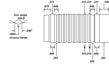
Lee's recommendations are a microgroove width of 0.040", a minimum band width of 0.010" and a groove side angle of 26 degrees. These length values are not written in stone but, for purposes of this demonstration we shall use them.
#1. Suppose you want an In-case length of 0.545", a crimp groove length of 0.045" and a gas check minimum shank length of 0.070
#2. Subtract the length of the crimp groove(s) and the length of the crimp groove interval(s) from the value defined in step #1. 0.545 - 0.045 = 0.500
#3. Subtract the pre-determined length of the gas check shank from the value determined in step #2 0.500 - 0.070 = 0.430
#4. Define a micro-groove unit as one groove width + one band width 0.040 + 0.010 = 0.050
#5. Divide the value determined in step #3 by the value determined in step #4 0.43 / 0.050 = 8.6 Round this value DOWN to the nearest whole number. Step #5 value = 8
#6. Multiply the value in step #5 by the value in step #4 8 x 0.050 = 0.400
#7. Subtract the value in step #6 from the value in step #3 0.430 - 0.400 = 0.030. (If this value is less than the length of one body band, you may wish to re-evaluate the lengths and ratio of the body bands and the grease grooves)
#8. Add the Gas Check value in step #1 + the value in step #7 0.070 + 0.030 = 0.100 This is the length of the Base Band.
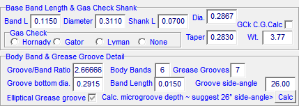
#9. Edit the Crimp Groove Lower Band length to be that of a body band length ( 0.015 )

#10. Edit the Base Band Length to be that of the value determined in #8 ( 0.100 )
#11. Edit the Groove/Band Ratio. ( 0.040 / 0.015 = 2.66666667
#12. Subtract 1 from the value found in step #5 and Enter the result into the Body Bands field value ( 8 - 1 = 7 )
#13. Repeatably press the Tab Key and it should auto-calculate the band length.
#14. Edit the Groove side-angle value. Suggested value is 26 degrees.
#15. Click the "Calc" button to auto-calculate the Groove bottom diameter and click the Calculate Button below.
The software uses the following algorithm to calculate the Groove bottom diameter:
Groove bottom diameter = Cast Diameter Value - [ Tan( groove side angle ) x Groove Length ]
If desired, some of the length of the base band may be subtracted and added to the length of the Crimp Groove Lower Band and the micro-groove values will not be altered.
The length of the gas check shank may also be increased while the base band length is decreased by the same amount without affecting the micro-groove values.


Copyright ©, TMT Enterprises 2012


