Contents
- Index
Dimension Sketch Icons
After a Dimension Sketch is drawn it may be saved to the computer as either a Bitmap image or a Jpeg image.
It is possible to save the image with a small icon or icons of the bullet located on the image.
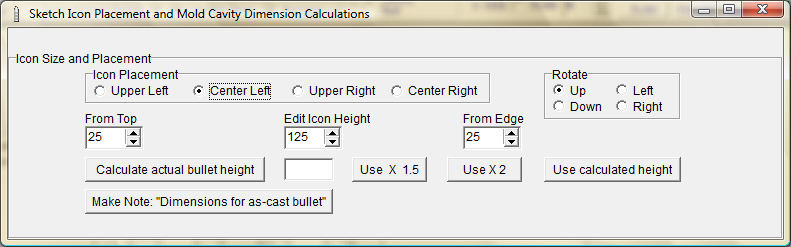
Clicking the  button will open the Icon Configuration module where the size, aspect and location of the icon on the sketch may be determined.
While in the Icon Configuration module.
Select the position of the icon from the "Icon Placement" radio button group.
Choose the rotation aspect of the icon from the "Rotate" radio button group.
Edit the distance from the edge of the sketch to place the icon.
Edit the pixel height of the icon.
Edit the distance from the top of the sketch to place the icon.
To draw the Icon to approximately the actual bullet height, click the button to calculate the height then click the "Use calculated Height" button This will edit the Pixel Height spin-edit field.
The "Use x 1.5" and "Use x 2" buttons will multiply the value shown in the spin-edit field by either 1.5 or 2 and change that value accordingly.
The two "Make Note" buttons will place a note in the Bullet Comments form in the General Comments and Comments #3 fields. These comments will be displayed on the sketch the next time the "Draw Sketch" button is clicked. To remove these comments from the sketch or edit them, go to the Main Form and click on the "Bullet Comments" button at the bottom of the Main Form.
On the Sketch Form, click the  button to draw the bullet icon at the spot determined by the settings in the Icon Configuration Form.
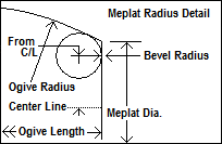
When designing a bullet with a flat meplate, if the Main Form Nose Detail indicates that the meplate edges are to be drawn with a radius, 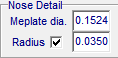 the indicated radius is then incorporated into the sketch. When the mold maker is setting up, the dimensions of the meplate and ogive length may be confusing. As an aid in determining the correct values to use, the diagram shown below may be drawn upon the Dimension Sketch at a spot that is determined by the settings in the Icon Configuration Form.
After the settings are determined. click the  button to draw the diagram at the indicated spot on the sketch. The size values in the Icon Configuration Form will have no effect on the size of the diagram as it is drawn on the sketch.
Copyright ©, TMT Enterprises 2012