Contents
Draw the Chamber Image
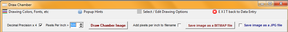
Control Box
Quick steps to draw the chamber overlay image
1. (Optional) Check the Precision x 4 checkbox to show all values to four decimal places instead of the default three decimal places.
2. Use the default value or Select a Pixels Per Inch scale that is large enough to visually examine the bullet fit.
3. Click the "Draw Chamber Image" button to draw an image of the chamber using the values stored in the selected chamber data record.
4. Check the Add pixels per Inch in filename checkbox to add the pixels per inch scale value to the filename of the saved image.
5. Click the "Save Image To A File" button to store the drawing as an image file on your computer.
Do not check the Save the image as a JPG file checkbox when saving the chamber drawing when it is to be used in an overlay image. The image must be in BITMAP format to work in the overlay module.
Menu Items for the chamber image
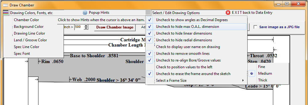
Drawing Colors, Fonts, etc.
Choose drawing colors and text fonts for the various segments of the chamber image
Select /Edit Drawing Options
Check or un-check the Decimal Degrees menu item to switch angle value displays from decimal values to degrees-minutes-seconds values.
Check or un-check the hide max O.A.L. menu item to display a maximum cartridge length arrow and value on the drawing.
Check or un-check the hide radial dimensions and hide linear dimensions menu items to display either linear or radial dimension values and arrows on the drawn image.
Check or un-check the display user name menu item to display the user name stored in the User Identity in the copyright text at the lower right of the chamber drawing.
Check or un-check the smooth lines menu item to blend drawing line colors to the adjacent pixel colors.
Check or un-check the re-align Bore/Groove values and position values to the left menu items to reposition throat, bore and groove values in the drawings of chamber with short O.A.L. and throat lengths.
Check or un-check the erase the frame around the sketch menu item.
Select the drawing frame width with the radio buttons at the lower right of the menu to determine the width of the outline to be drawn around the chamber image when the Draw Frame menu item is checked.
Click the Save Image to a file button, when the save module opens, locate the folder where the chamber draw module is loaded on your computer and create a folder labeled with the appropriate caliber name for each set of chamber images that are created.
On computers with a 32 bit operating system, the folder will normally be located at:
C:\Program Files\TMT\Precision\AllNew\Draw\ChamberPics\
On computers with a 64 bit operating system, the folder will normally be located at:
C:\Program Files (x86)\TMT\Precision\AllNew\Draw\ChamberPics\
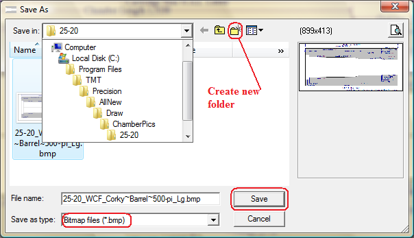
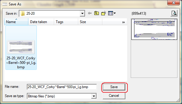
Save the bitmap image of the chamber in the folder labeled with the caliber name.
Copyright © 2014. TMT Enterprises. All rights reserved.