Contents
- Index
How to design a jacketed boat tail bullet
A separate design module for jacketed bullets is not yet available. However, the Cast Bullet Design ~ Advanced module may be configured to draw/design either cast or jacketed bullets.
In order to properly design a bullet to fit a specific firearm, cartridge/chamber/application design, the Cast Bullet Design 5 ~ Ultimate module should also be purchased downloaded along with the Cast Bullet Design 5 ~ Advanced module.
Below is an image of an experimental jacketed intended to be a fitted bullet to a Browning Medallion .280 Remington.
i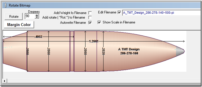
The design is intended to be a glove fit to the case neck length and the leade angle at the end of the freebore,The secant ogive matches the junction angle to the bullet body to the leade angle of the rifeling.
An impact slug impression is needed to obtain the exact chamber dimensions to be entered into the Ultimate Chamber Design module .
The Chamber Design / Bullet Design Unit is then used to create the initial critical dimension required to fit the Chamber and Cartridge configuration.
The initial design is then sent to the Cast Bullet Design~ Ultimate module to be transformed into a Design Dimension Sketch and also a Scaled Overlay Drawing.
Now the Ultimate Over-Lay module can be used to display the chamber configuration, cartridge dimensions and initial bullet design to determine the changes needed to conform to the expected design.
Returning to the Advanced Design module:
Check the "Jacketed" checkbox.
The rear bore ride value is increased to the bore groove diameter, making a match to the leade angle.
Make sure that the bore ride length is the same as the leade length calculate in the Chamber Design module.
To design a boat tail bullet:
1. The Bevel Base option is selected.
2. Set the shank length to match the boat tail length. Set the Bevel Base Dia. to match the boat tail diameter.
To add a rebated boat tail to an existing bullet design length
1. The gas check option is selected.
2. Set the base band diameter to the as-cast diameter.
3. Set the gas check shank length to match the boat tail length.
4. Set the gas check end diameter to the boat tail end diameter.
5. Set the gas check front diameter to the desired rebate front diameter.
6. Set the grease groove side angle to approximately 70 - 55 deg.
7. Add the boat tail length to the bullet length.
8. Add the boat tail length to the in-case length.
9. Subtract the gas check front diameter from the as-cast diameter, divide the result by two, add that value to the boat tail length then set the base band length to the result.
To design the knurled portion of the jacketed bullet, the square crimp groove option is selected.
Use the spin edit arrows to select the desired width of the knurl.
Set the crimp groove diameter to the desired depth.
Set the Crimp Groove lower Band Length to the changed in-case length MINUS the boat tail length. (only if rebated )
The Base Band Length is set to equal the Boat Tail length. (not rebated)
The Groove Band Ratio is set to 1.
The Number of bands is set to 0.
Grease Groove Bottom Dia.:
If a rebated boat tail is designed, set the groove diameter to the same value as the as cast diameter and set the groove side angle to approx. 70 - 55 degrees.
If a non rebated boat tail is designed, set the groove diameter to the same value as the as-cast diameter and set the groove side angle to 89.5 degrees.
The match the Secant Ogive angle to the bore leade angle:
Set the desired meplate diameter and calculate.
Increase or decrease the overall bullet length until bullet weight is slightly more than the target weight.
Select the Secant Ogive option.
Open the Secant Ogive editor with the button and incrementally increase the "Ogive Radius in inches" until the "Secant Offset Angle" matches the Bore Leade angle.
Finally, tweak the overall bullet length and the secant ogive radius until the desired weight is achieved.
In the Bullet Specs module, open the "Deatils" tab and check the "Show Gas Check Slope" checkbox.
Draw the bullet specs to check things out.
Open the Bulelt Design Draw module:
Select the "Custom " radio button option.
Set the "Custom Pixels per inch" field to match the scale of your chamber and cartridge drawings.
Check the"Draw a gas check bevel" checkbox.
Un-check the " Draw the Gas Check" checkbox.
Check the "Label the drawing" checkbox.
Optionally, check the "Label the drawing" and "Precision X 4" checkboxes.
Optionally, check the "Draw lead tip" and edit the length of the lead tip.
Draw the Bullet.
Click the "Rotate" button.
Rotate the bullet drawing 90 degrees. and save to the folder with the chamber and cartridge drawings.
Now, open the Overlay Module, load the chamber, cartridge and bullet images to examine the fit of the components.
To enable more critical visual examinations of the dimensions, draw all of the overlay images to a scale of 1,000 pixels per inch.
