Contents
Chamber Throat/Leade Design
Click to Jump to:
Neck Diameter ~ Calc Shoulder Angle ~ Start Chamber Draw module ~ Calc Head Space ~ Radius Shoulder ~ Throat, Free bore, Leade Area
The chamber / cartridge Radial tolerances from the breech to the neck area are a function of cartridge application (Target, Hunting, Plinking, Self Defense, etc.). This tutorial will use Radial fit tolerances from the chamber breech to the chamber neck that will allow the cartridge to chamber. The designer of the chamber may determine what will work best for a particular application.
This section will deal primarily with the chamber's linear dimensions and radial neck, throat, leade dimensions that will accommodate and fall within the Cast Bullet Design Parameters used to design a bullet for a particular chamber.
Start with a determination of the linear and radial dimensions of a cartridge loaded with the bullet sized to 1 or two thousandths over the barrel groove diameter and seated to the desired O.A.L.
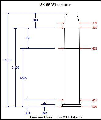
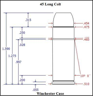
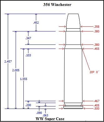
These images show the typical dimensions that will need to be measured and noted for various cartridges.

A 280 Remington R.P. case loaded with an R.C.B.S. 7MM-145-SIL cast bullet will demonstrate most of the procedures used to set up a custom chamber designed around a specific cartridge.
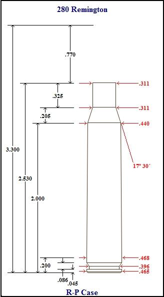
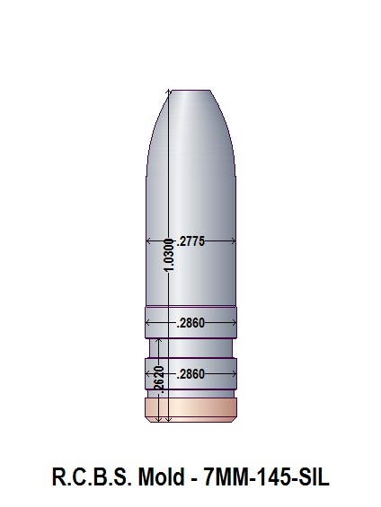
The barrel groove diameter is 0.285" and the bore diameter is 0.278"
The RCBS bullet is sized to 0.286" and has a bore riding nose diameter of 0.278"
Loading the 1.03" RCBS bullet to the base of the 0.325" neck length will leave an out-case length of 0.705", resulting in a cartridge O.A.L. of 3.235"
Neck Diameter
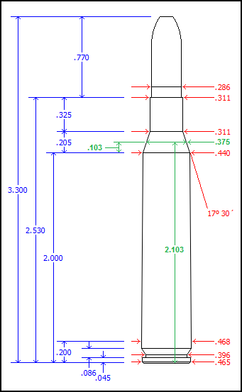
The R.P. case neck thickness is 0.0125". When loaded with the 0.285" bullet, the neck diameter is 0.311".
Back to Top
Shoulder Angle
If the shoulder angle is not known, the angle may be determined as follows:
Using a scientific calculator, set in the Degree Mode, apply the Arc tan (or tan-1) function to the number obtained by subtracting the cartridge neck diameter from the shoulder diameter, dividing the result by two and then dividing that number by the length of the shoulder portion to find the angle of the shoulder:
Arc tan ( [ Shoulder dia - Neck dia ] / 2 / Shoulder length ) = Shoulder angle.
[ 0.440 - 0.311 ] / 2 / 0.205 = 0.315
Arc tan ( 0.315 ) = 17.48 = 17.5 degrees.
Using the dimensions in the sketch, open the Cartridge Module to draw and save a 1,000 pixels-per-inch scaled image of the sized R.P. case. with a trim-to length of 2.530", loaded with a bullet diameter of 0.286" and a case neck diameter of 0.311".
Back to Top
Chamber Draw Module
Open the Bullet Design Module, draw and save a no-margin,1,000 pixels-per-inch, scaled image of the RCBS bullet.
The designer must determine the chamber/cartridge clearance tolerances to accommodate the intended application of the cartridge. This tutorial will use an arbitrary diameter clearance tolerance of 0.002", a head space clearance of 0.002" and a chamber length tolerance of 0.005".
Open the Chamber Design module, select the chamber dimensions tab then select a caliber name, enter the Reamer-Mfg. then select the Chamber and Rim types.
Enter a chamber length, consisting of the Cartridge trim-to length plus the tolerance of 0.005" = 2.540" (The head space tolerance 0f 0.002" will be set when determining the Base-to-Shoulder distance)
Enter the shoulder dia. of 0.44" + 0.002" = 0.442"
SAAMI specs frequently specify a chamber shoulder angle that is 0.25 degrees less than the cartridge shoulder angle so you can either enter a shoulder angle of 17.25 degrees or keep it the same as the cartridge shoulder angle of 17.5 degrees.
Enter the diameter of the neck at the shoulder, 0.311" + 0.002" = 0.313".
Exit the neck diameter field and the software will calculate a shoulder length of 0.2046".
Enter the end neck diameter of 0.311" + 0.002" = 0.313".
At this time, enter the neck length of the cartridge, 0.325" + 0.005" tolerance = 0.330". Upon exiting the field, the software will calculate a Base-to-Shoulder length. This value will need to be recalculated later to set up the proper head space length.
Enter a Web Dia. 1 value of the cartridge web dia + 0.004" = 0.472".
Enter a Web Length of 0.200".
Enter a Web Dia 2 value of the cartridge web dia + 0.002" = 0.472".
Since this is a rimless cartridge leave the Rim Dia and Rim Thickness fields blank.
(If the cartridge is a rimmed or semi rimmed cartridge, add 0.002" to the rim diameter and 0.002" to the rim thickness then enter those values.)
(If the cartridge is a belted cartridge, add 0.002" to the distance from the cartridge base to the forward edge of the belt and enter the value into the Belt Length field.)
Back to Top
Determining Head Space Values
The head space of a rimless cartridge is measured from a reference diameter located at approximately the mid point of the chamber shoulder to the breech or bolt at the rear of the chamber. This value is the sum of the head space tolerance ( 0.002" ) + the distance from the same reference diameter on the cartridge shoulder to the cartridge base. This distance must first be calculated (or measured) and the Chamber Base-to-Shoulder distance must be configured to reflect that value.
The shoulder reference diameter value that is commonly used to determine head space on the 30-06 class of cartridges is 0.375".
The cartridge head space value is the Base-to-Shoulder value + the linear distance from the cartridge shoulder to the point where the shoulder has the reference diameter of 0.375".
We can either calculate the head space distance by using the Base to Shoulder value or measure the distance using a pair of calipers.
To Measure the head space distance, set and lock the calipers at 0.375", place the cartridge shoulder into the caliper jaws and, keeping the cartridge perpendicular to the caliper jaws, rotate the cartridge, the sharp edge of the jaws will make a thin mark on the shoulder at a diameter of 0.375". Now, carefully measure the distance from that reference mark to the base of the cartridge and add the 0.002" head space tolerance.
2.102 + 0.002 = a head space value of 2.104
The Measured Head space Value is 2.1040"
To determine the head space distance through calculations, subtract the reference diameter of 0.375" from the cartridge shoulder diameter and divide that difference by 2 now divide that value by the Tangent of the shoulder angle and add that number to the cartridge Base to Shoulder value.
Tan( 17.5 deg. ) = 0.3153
( 0.440" - 0.375" ) / 2 / 0.3153 = 0.10308
2.000" + 0.10308' = 2.10308" + 0.002" tolerance. = a head space value of 2.10508"
The Calculated Head space Value is 2.10508"
Now we need to use that head space distance to calculate the Base to Shoulder distance for the chamber.
First, determine the chamber shoulder diameter by adding the chosen tolerance to the cartridge shoulder diameter.
Subtract the reference diameter of 0.375 from the chamber shoulder diameter and divide the difference by two then divide that value by the tangent of the shoulder angle and subtract that number from the cartridge head space value.
Tan( 17.25 deg. ) = 0.31051
( 0.442" - 0..375" ) / 2 / 0.31051 = 0.1789
2.10508 - 0.1079 = 1.9972 = chamber Base to Shoulder value.
Enter 1.9972 in the Base to Shoulder field. upon exiting, the software will calculate a neck length of 0.3351".
Back to Top
Determine Accurate Values for a Radius Shoulder and Neck
When the shoulder of a cartridge is radius, there is no defined point at which the Shoulder Diameter and Base-to-Shoulder measurements can be made. A fairly close estimate may be made of the values but a precise value would be better. Using a good set of steel calipers with sharp edges on the jaws, quite accurate measurements may be made from the cartridge case to calculate the precise Chamber Shoulder Diameter and Base-to-Shoulder values.
A sketch using the dimensions of a re-sized, loaded, 30-30 cartridge case will be used to demonstrate the measurements and calculations needed.
The shoulder angle must be determined from a published source as it can not be easily calculated from the radius corners. In this case, SAAMI specs give the 30-30 cartridge angle as 15° 39'. Decimal degrees will need to be used in the calculations so divide the 39' by 60' to arrive at the decimal value of 15.65 degrees.
When setting and locking the calipers to scribe the linear distances on the cartridge case, it helps to use values that may be evenly divided by 5 or 10, such as 1.500", 0.250", 1.250", etc.
Measured dimension values needed for the calculations are labeled on the sketch as:
"A", "B", "C", and "L", "O", "W"
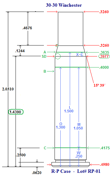
Set the calipers at a length that positions one jaw at the approximate mid point of the cartridge shoulder. For this 30-30 cartridge, the distance was set at 1.500".
Record this distance and label the value as "L".
Holding one jaw firmly square upon the base and rotate the case within the jaws, using the sharp edge of the opposite jaw to scribe a light line around the circumference of the shoulder mid point.
Next, set and lock a distance that will position the caliper jaw on the case body, near the shoulder. This arbitrary distance was set at 1.300"
Record this distance and label the value as "O".
Using the same procedure as before, scribe a light line around the circumference of the body.
Now, set and lock a distance that is just forward of the rim at the largest dimension on the case web.This distance was set at 0.250".
Record this distance and label the value as "W".
Now, using the calipers, determine the diameter values of the scribe marks on the case.
Carefully slide one jaw up the shoulder and you can feel the jaw stop in the scribe line. Close the caliper jaws and position the opposite jaw in the scribe line on the opposite side of the shoulder and read the diameter of the shoulder at the scribe. This reading was 0.3635".
Record this diameter and label the value as "A"
Using the same method, measure the diameter of the scribe line at the distance labeled "O", This reading was 0.4000"
Record this diameter and label the value as "B".
Finally, measure the diameter of the scribe line on the case web. This reading was 0.4175".
Record this diameter and label the value as "C".
Using these 6 measurements and the shoulder angle, the precise junction of body and shoulder can be calculated.
A = 0.3635
B = 0.4000
C= 0.4175
O = 1.300
W = 0.250
3 more variables need to be determined and labeled to make the formula less complicated.
The Tangent of the shoulder angle is Tan( 15.65° ) = 0.280145.
Record this value and label as "T"
T = 0.289145
K = L - W = 1.250
M = 0 - W = 1.050
X will be the unknown that is the distance from the point of the shoulder to the scribed line at the distance "L"
This are the two functions Base to Shoulder Distance.
X = ( M *[ C - A ] + K*[ B - C ] ) / ( 2*M*T + B - C )
BS = L - X
Here is how it works
M *[ C - A ] + K*[ B - C ]
1.05 * ( 0.4175 - 0.3635 ) + 1.25 * ( 0.4000 -0.4175 ) = 0.034825
( 2*M*T + B - C )
( 2 * 1.05 * 0.289145 + 0.4000 - 0.4175 ) = 0.570806
0.034825 / 0.570806 = 0.06101
X = 0.06101
BS = L - X
1.5 - 0.06101 = 1.4389
The Base-to-Shoulder distance is 1.4390"
Find the Shoulder Diameter using this formula:
SD = X * T * 2 + A
.0.06101 * 0.289145 * 2 + 0.3635 = 0.3977
The Shoulder Diameter is 0.3977"
Back to Top
Determine the dimension of the Step, Free bore and Leade
Bullet Design Paramaters suggest that, for best accuracy and minimal leading, the bullet should be as completely supported by the chamber throat as possible.
Various driving band lengths and diameters, as well as bullet bore riding and nose configurations, will also influence the chamber step, free bore and leade designs.
Maintaining the step angle, at the end of the chamber, as close as possible to 45 degrees will help to minimize the unsupported portion at the chamber end.