Contents
- Index
Designing or drawing Jacketed Bullets
(Design using the Cast Bullet Design ~ Ultimate module})
(Print out step by step detail)
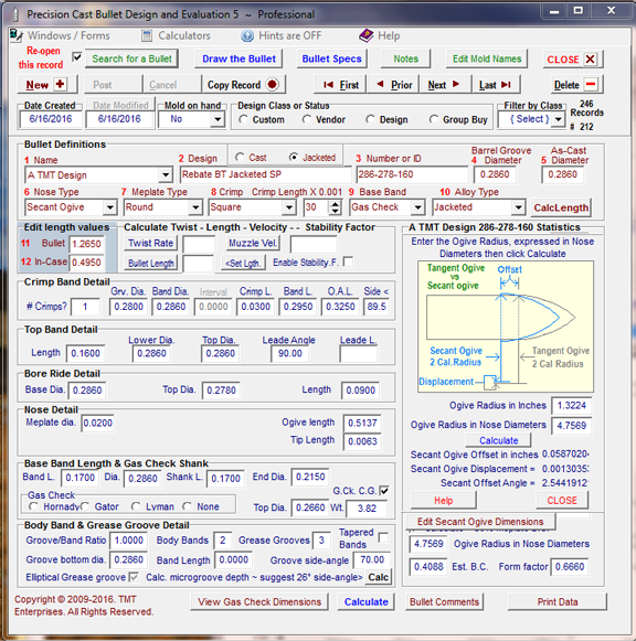
If a jacketed bullet is to be drawn, a data manipulation strategy will need to be followed.
The images below have the critical data fields outlined in red.
Click on each field outlined in RED to jump to the explanation of how the field should be edited to produce a jacketed bullet dimensions in the Main Form
Click on Back to Image to return to the image.
Click on each field outlined in RED to jump to the explanation of how the field should be edited to produce a jacketed bullet dimensions in the Main Form
Click on Back to Image to return to the image.
Click on each field outlined in RED to jump to the explanation of how the Icon editor should be configured to produce a jacketed bullet icon on the Bullet Sketch.
Click on the  at the upper left to return.
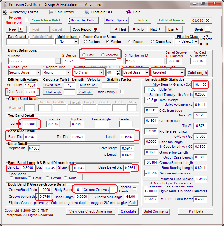
Select Cast or Jacketed Bullet:
Select the Jacketed radio button. This will set up the correct color and lead tip selection in the bullet drawing module.
(Back to Image 1)
Select Crimp or No Crimp:
Although the knurl on the jacketed bullet may be set up with the crimp feature, it is less hassle to simply use a long base band and a shallow grease groove or grooves to display a knurl or multiple knurls.
(Back to Image 1)
Select Bevel base or Plain Base:
A Completely flat base may be drawn on a jacketed bullet by selecting the Plain Base option but, by selecting the Bevel Base option, the drawing may display a slightly beveled base, a long radical boat tail or anything in between.
(Back to Image 1)
Select a Jacketed Alloy Density Value:
Select the Jacketed option to determine a standard alloy Specific Gravity value of 10.14 grams per cubic centimeter.
(Back to Image 1)
Edit the Alloy Density Value:
The alloy density value of 10.14 is a close approximation of the overall density of a jacketed bullet however, the value may be edited to more closely represent the alloy density of the selected design.
If the displayed dimensions of the bullet are correct but the calculated weight is substantially different that actual weight then divide the actual weight by the calculated weight and multiply the resulting value times the value displayed in the Alloy Density field and then edit the value with the result of the multiplication.
(Back to Image 1)
Determine the In Case Value:
The software will have initially entered a default value equal to 50% of the overall bullet length. Edit this value to the distance from the base of the bullet to the front of the knurl.
(Back to Image 1)
Set the Length of the Top Band Field:
The software will have initially entered a default value in the Top Band Detail Length field. Edit this length to 0.0000.
(Back to Image 1)
Edit the Bore Ride Segment Values
If the bullet diameter in front of the knurl is different than the main body diameter, use this segment to show this value. Also set the length of the bore ride to equal the distance from the front of the knurl to the start of the bullet ogive.
(Back to Image 1)
Edit the Base Band Length Value:
Edit the Band Length value to equal In-Case length minus the width of the Knurl.
Or the distance from the base of the bullet to the lower edge of the knurl. Whichever is the easiest to measure.
(Back to Image 1)
Edit the Bevel Base or Boat Tail Values:
If a slightly bevel base is desired multiply the bullet diameter by 0.05 and enter that value in the Shank Length field then subtract twice that value from the bullet diameter and enter that value in the Bevel Base Diameter field.
If a boat tail is to be drawn enter the length of the boat tail in the Shank Length and the small diameter of the boat tail in the Bevel Base Diameter field.
A rebated boat tail may be designed by manipulating the gas check options.
(Back to Image 1)
Set up the Groove Band segment to display the knurl:
Set the Groove/Band Ratio to 1.
Edit the Body Bands value to 0.
Edit the Grease Grooves value to 1.
(Back to Image 1)
Edit the Groove Dia. Value:
Edit this value to equal the diameter of the knurled section of the bullet
(Back to Image 1)
Edit the Groove Side Angle Value:
This value may be edited with a value from 90 degrees to 45 degrees or whatever displays best in the drawing and sketch
(Back to Image 1)
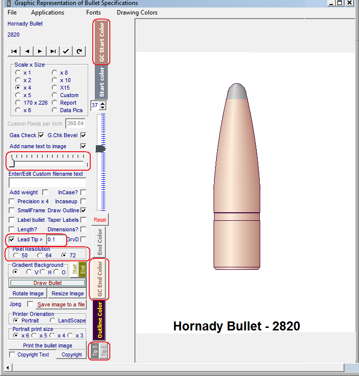
Edit the color of the jacketed image:
The Color of the jacket is determined by the color selected for a gas check drawn on a Cast bullet.
Clicking on the "GC Start Color" button will open a color dialog window where the darkest color of the gradient may be selected.
Clicking on the "GC End Color" button will ope a color dialog window where the lightest color of the gradient may be selected.
Clicking the small "Reset" button will return all color and text values to the default settings.
(Back to Image 2)
Adjust the size of the Label Text:
The Size of the label at the bottom of the image may be adjusted with this slider. Trial and error is a good method to use to determine the best setting for a particular image and size.
(Back to Image 2)
Edit the length of the lead tip:
The software automatically draws a soft lead tip on all jacketed drawings and selects a length of 0.05" inches for the length of the tip.
Edit the field for the length of the tip to be displayed.
(Back to Image 2)
Edit the size of the image within the frame size:
The default pixels per inch size to be drawn in the frame is set at 64. Selecting a larger or smaller value will adjust the size of the image withing the frame size that has been selected in the "Scale and Size" Radio Button selector at the top of the form
(Back to Image 2)
Edit the color of the lead tip drawn on the image:
The Gradient Color of the lead tip drawn on a jacketed bullet image is determined by the colors selected in color dialog windows opened by the two small buttons at the bottom of the form..
Clicking on the "Tip S" button will open a color dialog window where the darkest color of the gradient may be selected.
Clicking on the "Tip E" button will ope a color dialog window where the lightest color of the gradient may be selected.
Clicking the small "Reset" button will return all color and text values to the default settings.
(Back to Image 2)
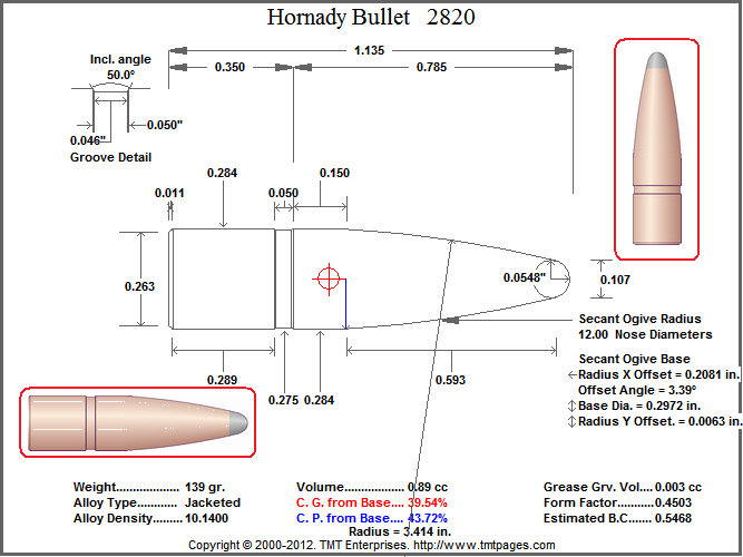
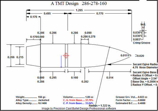
Designing a Rebated Boat Tail and an ogive to fit the bore leade angle
1. Select a Mold/Mfg name.
2. Enter a cryptic description of the design.
3. Check the "Jacketed" checkbox.
The rear bore ride value is increased to the bore groove diameter, making a match to the leade angle.
Make sure that the bore ride length is the same as the leade length calculate in the Chamber Design module.
The gas check option is selected:
Set the shank length to match the boat tail length. Set the End Dia. to match the boat tail diameter. Set the top dia. to the as-cast diameter.
To make a rebated boat tail, Set the gas check top diameter slightly smaller than the as-cast diameter and set the grease groove side angle to approximately 70 deg.
Add the boat tail length to the bullet length.
Add the boat tail length to the in-case length.
Change the Base Band length to the Boat Tail Length.
The Square crimp groove is selected.
Use the spin edit arrows to select the desired width of the groove.
Set the crimp groove diameter to the desired depth.
Set the Crimp Groove lower Band Length to the changed in-case length MINUS the Boat Tail Length.
The Base Band Length is set to equal the Boat Tail length.
The Groove Band Ratio is set to 1.
The Number of bands is set to 0.
Grease Groove Bottom Dia.:
If a rebated boat tail is designed, set the groove diameter to the same value as the Gas check top diameter and set the groove side angle to approximately. 70 degrees.
If a straight boat tail is designed, set the groove diameter to the same value as the as-cast diameter and set the groove side angle to 89.5 degrees.
The Secant Ogive:
Set the desired meplate diameter and calculate.
Increase or decrease the overall bullet length until bullet weight is slightly more than the target weight.
Select the Secant Ogive option.
Open the Secant Ogive editor with the button and incrementally increase the "Ogive Radius in inches" until the "Secant Offset Angle" matches the Bore Leade angle. Example: Angle = ( ArcTan((GrooveDia. - BoreDia.) / 2 / LeadeLength) ( ArcTan( (0.286" - 0.278" ) / 2 / 0.090") = 2.544 degrees.
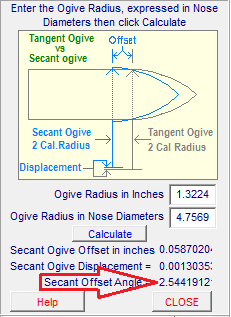 Finally, tweak the overall bullet length and the secant ogive radius until the desired weight is achieved.
Draw the bullet specks to check things out.
Open the Draw module:
Select the "Custom " radio button option.
Set the Custom Pixels per inch field to match the scale of your chamber and cartridge drawings.
UN-CHECK the Gas check bevel checkbox.
Check the Label the drawing checkbox.
Optionally, check the Label the drawing and Precision X 4 checkboxes.
Optionally, check the draw lead tip and edit the length of the lead tip.
Draw the Bullet.
Rotate the bullet drawing 90 degrees. and save to the folder with the chamber and cartridge drawings.
Finally, tweak the overall bullet length and the secant ogive radius until the desired weight is achieved.
Draw the bullet specks to check things out.
Open the Draw module:
Select the "Custom " radio button option.
Set the Custom Pixels per inch field to match the scale of your chamber and cartridge drawings.
UN-CHECK the Gas check bevel checkbox.
Check the Label the drawing checkbox.
Optionally, check the Label the drawing and Precision X 4 checkboxes.
Optionally, check the draw lead tip and edit the length of the lead tip.
Draw the Bullet.
Rotate the bullet drawing 90 degrees. and save to the folder with the chamber and cartridge drawings.
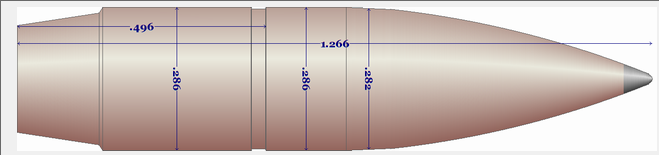
Now open the Overlay Module using a 500pixel per inch setting and examine the fit of the components.
To reliably perform critical visual examinations of the dimensions, construct all the overlay drawings for display in the Overlay Module using a 1,000 pixel per inch setting
Copyright ©, TMT Enterprises 2016