Contents
- Index
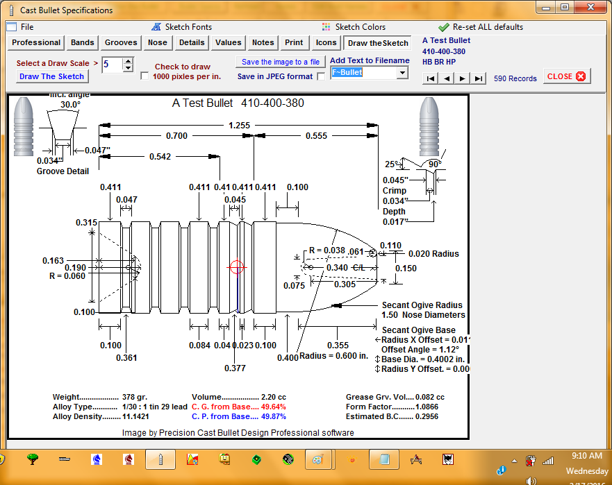
Creating the Dimension Sketch
Each sketch unit or dimension notation may be hidden or displayed by toggling the appropriate checkboxes displayed in each tabbed page.
(Click on any of the menu items at the top of the image, or the page tabs below the menu items, to jump to the help topic)
_____________________O___________________
The Show Hints menu item will toggle the Hint procedure on or off.
When the Hint procedure is ON, positioning the mouse cursor over a data control will cause a hint to appear for a short time.
Jump Back to Top
_____________________O___________________
_____________________O___________________
Various Font styles, sizes and colors may be selected from a font dialog for each section of values and dimensions displayed on the sketch.
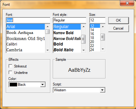
Jump Back to Top
_____________________O___________________
_____________________O___________________
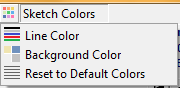
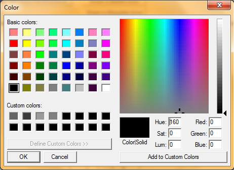
Colors for the line drawings and back ground may be selected from a color dialog box for the sketch drawing.
_____________________O___________________
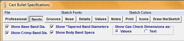
Checking and un-checking the checkboxes in this panel will cause
Individual sketch dimension values to be toggled on or off.
The gas check dimension values to be displayed either as a base and shank dimension or as text that instructs the mold maker to cut the mold gas check shank to fit a specific brand and size of gas check.
Jump Back to Top
_____________________O___________________
_____________________O___________________
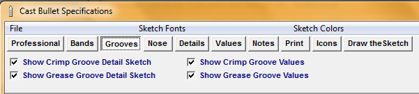
Checking and un-checking the checkboxes in this panel will cause:
The grease and crimp groove detail sketch inserts to be toggled on and off.
The Sketch dimension values of grease grooves and crimp grooves to be toggled on and off.
Jump Back to Top
_____________________O___________________
_____________________O___________________
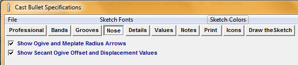
Checking and un-checking the checkboxes in this panel will cause
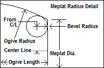
The radius arrows for the ogive radius and flat meplate round-off radius to be toggled on an off.
The Secant Offset dimension values to be toggled on and off.
Jump Back to Top
_____________________O___________________
_____________________O___________________
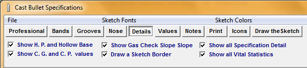
Checking and un-checking the checkboxes in this panel will cause:
The hollow point and hollow base dimension values to be toggled on and off.
The slope or taper from the base band down to the gas check detail to be toggled on and off.
Center of gravity and center of pressure indicator and arrow to be toggled on and off.
The drawing of a sketch border to be toggled on and off.
The display of all sketch dimension references and values to be toggled on and off.
The display of all vital statistics at the lower portion of the sketch to be toggled on and off.
Jump Back to Top
_____________________O___________________
_____________________O___________________
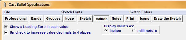
Checking and un-checking the checkboxes in this panel will cause:
The leading zero digit in each decimal value display to be toggled on and off.
Increasing or decreasing the number of decimal value from 3 to 4 to be toggled on and off.
Selecting the inches or millimeters radio button will display all sketch values in the selected unit of measurement.
Jump Back to Top
_____________________O___________________
_____________________O___________________
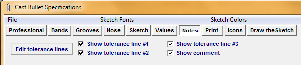
Three individual lines of tolerance or informational text may be displayed on the sketch.
A line of general comment text may also be displayed.
These notes, tolerances or comments may be created and edited in the Tolerance Editor by clicking on the "Edit tolerance lines" button
Checking and un-checking the checkboxes in this panel will cause
The radius arrows for the ogive radius and flat meplate round-off radius to be toggled on an off.
The Secant Offset dimension values to be toggled on and off.
Jump Back to Top
_____________________O___________________
_____________________O___________________
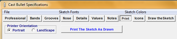
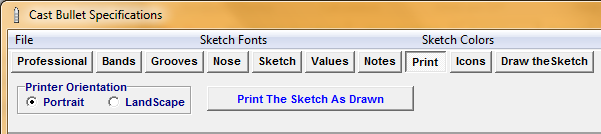
This tabbed panel will select the printer and print orientation to print the sketch image as displayed.
Jump Back to Top
_____________________O___________________
_____________________O___________________
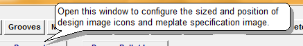
Small images of the bullet may be displayed at various positions on the sketch image.
The size and location of an icon may be determined by opening the Icon placement and Parameter window.
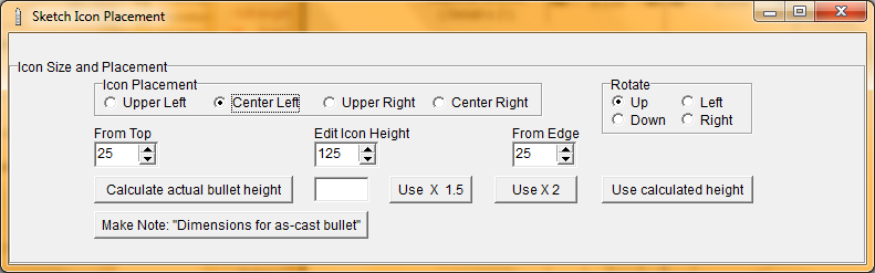
If multiple icons are desired, the Icon Parameter window must be edited for each position and size of an additional icon.
When a flat meplate edge radius is selected, a Meplate Radius Sketch Icon may be positioned and drawn on the sketch to assist in determining the proper positioning and placement of the radius.
Each bullet icon and/or meplate icon must be individually positioned using the Icon Parameter window.
Click the "Clear Icons" button to re-draw the sketch and delete any drawn icons.
Jump Back to Top
_____________________O___________________
_____________________O___________________
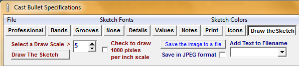
To increase or decrease the size of the sketch, use the Spin Edit unit to select drawing sizes between 4 and 12. Or check the box labeled "1,000 Pixels" to draw a sketch to a scale of 1,000 pixels to the inch.
Usually, whenever a specification adjustment change is made, the sketch will automatically re-draw. If this doesn't happen, click the button titled "Draw The Sketch".
Save the sketch image into the computer as either a jpeg or bitmap file by checking or un-checking the JPEG Format checkbox and click the "Save image to a file" button then select a destination folder from the save file dialog box.
You may add custom text to the saved file name by typing in or selecting pre-determined text from the "Add Text" window.
Jump Back to Top
_____________________O___________________
Copyright ©, TMT Enterprises 2016