Contents
- Index
Jacketed Bullet Design
Using the Cast Bullet Design ~ Ultimate module
A separate design module for jacketed bullets is not yet available. However, the Cast Bullet Design module may be configured to draw/design either cast or jacketed bullets.
In order to efficiently design a bullet for a specific firearm cartridge/chamber/application design, theCast Bullet Design ~ Ultimate module should be purchased and downloaded/installed after the Cast Bullet Design ~ Advanced module is installed.
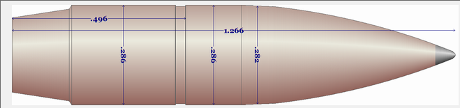
Below is an image of a jacketed boat tail design that I was experimenting with as a fitted bullet to my Browning Medallion .280 Remington.
The design is intended to be a glove fit to the case neck length and the leade angle at the end of the freebore,The secant ogive matches the junction angle to the bullet body to the leade angle of the rifeling.
An impact slug impression is needed to obtain the exact chamber dimensions to be entered into theUltimate Chamber Design moduleBullet Design Unit
The Chamber Design / Bullet Design Unitt is then used to create the initial critical dimension required to fit the Chamber and Cartridge configuration.
The initial design is then sent to the Cast Bullet Design~ Ultimate module to be transformed into a Design Dimension Sketch and also a Scaled Overlay Drawing.
Now the Ultimate Over-Lay module can be used to display the chamber configuration, cartridge dimensions and initial bullet design to determine the changes needed to conform to the expected design.
Returning to the Advanced Design module:
1. Select a Mold/Mfg name.
2. Enter a cryptic description of the design.
Check the "Jacketed" checkbox.
The rear bore ride value is increased to the bore groove diameter, making a match to the leade angle.
Make sure that the bore ride length is the same as the leade length calculate in the Chamber Design module.
The gas check option is selected:
Set the shank length to match the boat tail length. Set the End Dia. to match the boat tail diameter. Set the top dia. to the as-cast diameter.
To make a rebated boat tail, Set the gas check top diameter slightly smaller than the as-cast diameter and set the grease groove side angle to approximately 70 deg.
Add the boat tail length to the bullet length.
Add the boat tail length to the in-case length.
Change the Base Band length to the Boat Tail Length.
The Square crimp groove is selected.
Use the spin edit arrows to select the desired width of the groove.
Set the crimp groove diameter to the desired depth.
Set the Crimp Groove lower Band Length to the changed in-case length MINUS the Boat Tail Length.
The Base Band Length is set to equal the Boat Tail length.
The Groove Band Ratio is set to 1.
The Number of bands is set to 0.
Grease Groove Bottom Dia.:
If a rebated boat tail is designed, set the groove diameter to the same value as the Gas check top diameter and set the groove side angle to approximately. 70 degrees.
If a straight boat tail is designed, set the groove diameter to the same value as the as-cast diameter and set the groove side angle to 89.5 degrees.
The Secant Ogive:
Set the desired meplate diameter and calculate.
Increase or decrease the overall bullet length until bullet weight is slightly more than the target weight.
Select the Secant Ogive option.
Open the Secant Ogive editor with the button and incrementally increase the "Ogive Radius in inches" until the "Secant Offset Angle" matches the Bore Leade angle.
Finally, tweak the overall bullet length and the secant ogive radius until the desired weight is achieved.
Draw the bullet specks to check things out.
Open the Draw module:
Select the "Custom " radio button option.
Set the Custom Pixels per inch field to match the scale of your chamber and cartridge drawings.
UN-CHECK the Gas check bevel checkbox.
Check the Label the drawing checkbox.
Optionally, check the Label the drawing and Precision X 4 checkboxes.
Optionally, check the draw lead tip and edit the length of the lead tip.
Draw the Bullet.
Rotate the bullet drawing 90 degrees. and save to the folder with the chamber and cartridge drawings.
Now open the Overlay Module using a 500pixel per inch setting and examine the fit of the components.
To reliably perform critical visual examinations of the dimensions, construct all the overlay drawings for display in the Overlay Module using a 1,000 pixel per inch setting
Copyright ©, TMT Enterprises 2016