Contents
Basic steps for using the Cast Bullet Design ~ Ultimate software
Click the shortcut icon on your desktop to open the Cast Bullet Design ~ Ultimate Menu Bar

(Click on the icons in this image to open the help file topic related to each module)
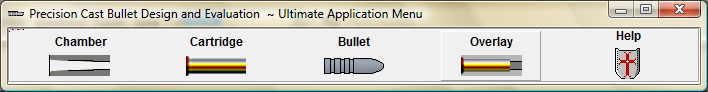
(Click on the Back Button at the upper left of the help file topic to return to this page)

For a condensed version of this page, go to Quick Start
For best imaging results, select your optimum monitor Screen Resolution
The bullet will be designed using pre-defined Bullet Parameters
Slug the barrel bore to determine groove and bore dimensions. (optional)
1. Find the chamber dimensions using:
Chamber cast method
Impact impression method.
Use reamer or SAAMI and C.P.I. chamber dimension values
2. In the Cast Bullet Design ~ Ultimate Menu Bar click the "Chamber" icon to open the Chamber Data Entry Module.
Select a Chamber Record or Create a new record and enter all Chamber dimension values in the tabbed page titled "Enter Chamber Dimensions".
Barrel Chambers.
Straight wall cartridge chambers.
Bottleneck cartridge chambers.
Rimless cartridge chambers.
Belted cartridge chambers.
Cylinder Chambers.
Rebated rim cut cylinders.
No rim cut cylinders..
Bottleneck Cylinder Chambers.
3. Click the "Draw Chamber Image" button to open the "Draw Chamber Image Module"
Select a scale large enough to clearly observe the bullet and cartridge fit to the throat and lead area.
Draw the chamber image.
Save the chamber image to a folder labeled with the appropriate chamber caliber name.
4. Return to the Data Entry module and open the Tabbed page titled Bullet Design
Make sure the "Edit Case Neck Dia > > >" check box is not checked then click the "Open Draw Cartridge" button to open and view the Cartridge Draw module.
Make sure that the Neck thickness value is correct.
The cartridge neck thickness value is a calculated field. If the value is not correct then enter a nominal bullet diameter in the "Bullet Dia." field.
Add twice the actual cartridge neck thickness to the bullet diameter and enter that value in the "Neck Dia. at Mouth" field.
Click the "Calc Shoulder Length" button is clicked , the software will enter the calculated Neck thickness value in the field.
5. Return to the Chamber Draw module and open the tabbed page labeled Bullet Design Page.
Enter a realistic muzzle velocity value and then, using the Tab key, step through the value entry fields and the software, using design parameters, will calculate a bullet length suitable to the twist rate and radial dimensions to fit the Chamber, bore, groove and cartridge dimension values
In the " 3. Calculation parameters" box, use the small up/down arrow buttons to select a minimum neck clearance value.
Check the "Edit Case Neck Dia > > >" check-box, open the Draw Cartridge Module and draw a cartridge image to the same scale as the Chamber Dimension image.
Save the cartridge image into the same folder as the chamber image.
Close the Cartridge Draw module.
6. Return to the Bullet Design page in the Chamber Draw module.
Send the calculated critical bullet dimension values to the Cast Bullet Design Module.
The module will open and draw a bullet with critical dimensions that will fit the chamber and cartridge measurements.
Click this button to open the complete Cast Bullet Design Module help file.
Edit the bullet dimension values to your preference and draw a bullet image to the same scale as the chamber dimension image. Rotate the bullet image. Locate the folder containing the chamber and cartridge case images and save the bullet bitmap image to the folder.
Open the Design Overlay Module and load the chamber, bullet and cartridge images. Adjust the positions of the cartridge and bullet overlay images to an exact fit to the chamber.
Make note of any changes that are needed in the bullet design then return to the Cast Bullet Design module, make the changes to a new drawing and, if satisfied with the fit, save the modified drawing to the chamber folder.
Re-load and re-draw the bullet image into the Overlay module and, if not satisfied with the fit, adjust the dimension values in the bullet design module, redraw the bullet, save the image then reload the bullet image into the Overlay module to re-check the fit to the throat and leade. Continue the check, re-design and fit process until you are satisfied with the final design.
Copyright © 2014. TMT Enterprises. All rights reserved.